Article Text

Abstract
AIMS To investigate the effects of artefacts on scanning laser polarimetry of the retinal nerve fibre layer.
METHODS Six eyes of six normal volunteers and an artificial nerve fibre layer were examined using the nerve fibre analyser II. The retinal nerve fibre layer thickness (RNFLT) was measured in each of four 90 degree quadrants, superior (S), temporal (T), inferior (I), and nasal (N), at 1.5 disc diameters from the disc margin. Study 1: Measurement in normal eyes. The amount of maximum error in RNFLT measurements was investigated as follows: (1) the intensity setting of the laser beam was changed to be as weak as possible or to be as strong as possible; (2) the intentional offsets of the laser beam axis in relation to the pupil were made in four directions; (3) the eye was rotated by shifting the head 45 or 90 degrees; (4) the right eye was measured by moving it to the left eye position on the head rest.Study 2: Measurements on an artificial nerve fibre layer. The birefringence measurements were confirmed with a plastic disc, which has a radial arrangement of birefringence. The plastic disc with black paper was fixed at the right eye position or the left eye position on the head rest. The retardation of the laser beam by the plastic disc on the black paper was measured. The retardation of the plastic disc was checked by an automatic birefringence evaluation system (ABR-10A, Uniopt Co, Ltd, Shizuoka).
RESULTS Study 1: The effects of the rotated eye and the measurement of the opposite eye position were significant. The eyes rotated 90 degrees showed quite a different pattern in which the thicker and thinner locations of the RNFLT are switched. The nasal RNFLT of the baseline and the 90 degree rotated eye are 41.9 (SD 6.0) μm and 122.5 (11.2) μm, respectively (p<0.0001, Scheffe multiple comparison test).Study 2: The uniform retardation of the plastic disc was observed with the ABR-10A. The NFA detects the retardation of the plastic disc which the retardation map showed as a double humped pattern.
CONCLUSIONS Study 2 indicated that the amount of corneal compensation was not small. The cause of significant influences by the rotated eyes and right eyes measurement in left eye position were thought to be incorrect corneal compensation. To increase the diagnostic ability of SLP, an improved compensation of the cornea is thought to be important.
- glaucoma
- nerve fibre layer thickness
- scanning laser polarimetry
- optic nerve head
- birefringence
- laser
Statistics from Altmetric.com
Scanning laser polarimetry (SLP) has been proposed as an objective and quantitative method for assessing the thickness of the retinal nerve fibre layer (RNFLT) in vivo.1-5 This technique estimates RNFLT based on the retardation of the laser beam which is caused by the birefringence of the nerve fibre layer.3 6-8 The high sensitivity, specificity, and reproducibility of this method has been reported.2 9-11Further development of this technique made it possible to detect abnormalities of RNFLT based on a normal database.12 This technique would seem to be a strong candidate as an effective diagnostic procedure for early glaucoma.
However, the RNFLT which were estimated with SLP were correlated with glaucomatous change in the superior and the inferior area of the optic disc, but not in its the temporal area.1 13 Morganet al report the comparison of the SLP measurement and histological measurement in which the nasal side of optic disc is not correlated and the temporal side of optic disc had a lower correlation coefficient than the superior or the inferior one.14 To improve the temporal and nasal measurements we need to investigate the properties of the SLP.
In this report, we have investigated the effects of artefacts on scanning laser polarimetry of the RNFLT.
Study 1: Measurements on normal eyes
MATERIALS AND METHODS
Six right eyes of six normal volunteers who were free from ophthalmic and systemic disease were studied. They ranged in age from 25 years to 36 years. The refractive error of the subjects ranged from −2.75 dioptres to +0.25 dioptres.
Nerve fibre thickness profiles were obtained using the nerve fibre analyser II (NFA II, Laser Diagnostic Technologies, San Diego, CA, USA) Version 2.1.17 beta, as described elsewhere in detail.1-3 6-10 15 Using the NFA, a polarisation image, which is a topographic image representing the RNFLT at each image pixel, was obtained in an array of 256 × 256 pixels. The RNFLT was measured within a 10 pixel-wide band located at a distance of 1.5 disc diameters from the disc margin. The mean thickness in each of the four 90 degree quadrants, superior (S), temporal (T), inferior (I), and nasal (N), were generated from each image. In this study, we have used the micrometre (μm) as a value of thickness, rather than the degree unit as a retardation of the polarised laser beam, because it is thickness that is required for diagnosis of glaucoma. All measurements were performed consecutively on each subject by one trained operator (SK). The baseline recordings were obtained under the following conditions: the subject's head was placed as upright as possible in the chin rest, pupils were undilated, the eyelids were opened as wide as possible, and ambient lights remained on. When the examiner had properly focused a ring-shaped target onto the iris and centred the target around the patient's pupil, a fundus image was seen on the liquid crystal display (LCD) monitor. The intensity of the illuminating laser light was adjusted to display as much blue speckle as possible, without any red speckle on the LCD monitor. The nerve fibre layer thickness was measured three times for each eye.
The range of error in RNFLT measurements was investigated under the following four conditions:
- (1)
The intensity setting of the laser beam was changed to be as weak as possible and to be as strong as possible. The recordings with maximum laser beam strength were obtained under the following conditions: the intensity of the illuminating laser light was adjusted to as much as possible within the range displaying fundus images in the red speckle on LCD monitor. The recordings with minimum laser beam were obtained under following conditions: the intensity of the illuminating laser light was adjusted to as low intensity as possible displaying the fundus images on LCD monitor.
- (2)
The intentional offset of the laser beam axis and pupil was made in four directions. Comparisons were made between RNFLT by the baseline recording and by recording with shifting the laser beam axis towards the superior, temporal, inferior, or nasal side of the pupil. The laser beam axis was shifted as much as possible, after focusing the ring-shaped target onto the iris and centring the target around the subject's pupil. As we shifted the beam the fundus image was lost. We stopped shifting the beam before the image was lost. We shifted about 5 mm.
- (3)
The eye was rotated by tilting the head 45 or 90 degrees. The conditions of measurements were the same as the baseline recordings except that the subjects shifted their heads to the left at 45 or 90 degrees. The nerve fibre layer thickness was measured three times for one eye.
- (4)
The right eye was measured by moving it to the left eye position on the head rest. The eye and the head were upright. This condition is almost the same as baseline measurements except the NFA automatically decided the right eye was the left eye.
RESULTS
The reproducibility of the baseline recordings was very good. The mean coefficient of the variations were 5.3%, 7.7%, 6.4%, and 6.5% for the S, T, I, and N, respectively.
Condition 1: Intensity setting of the laser beam
The maximum or the minimum laser beam intensity effect on measurements was not significant (p= 0.102, one way ANOVA) (Table 1) All images showed the double humped pattern of RNFLT; thicker at S and I, thinner at T and N.
Effects of the changed intensities of the laser beam and the off set of the laser beam axis
Condition 2: Offset of the laser beam axis
The influences of the offset of the laser beam axis and pupil to measurements were shown in Table 1. The shifts affected little. All images showed the same double humped pattern of RNFLT as in condition 1 and baselines.
Condition 3: Eye rotation
The reproducibility of the rotated eye recordings was good. The mean coefficient of the variations were 9.6%, 6.5%, 6.0%, and 4.2% for the S, T, I, and N, respectively. All images showed the double humped pattern of RNFLT; thicker at the vertical area, thinner at the horizontal area (Fig 1). An opposite arrangement to the baseline images should have been observed because the thicker area on the baseline images, S and I, was turned to the horizontal area by a 90 degree rotation of eye. The images thicker at vertical and thinner at horizontal area were confirmed on the images with a 45 degree rotation of the eye. The changes between baseline images and images with 90 degree rotation of the eye were statistically significant (p<0.0001, Scheffe multiple comparison test).

The rotated eye's influence on the retardation map. The top photographs of fundus images show the degree of rotation at 0 degrees (top left), 45 degrees (top centre), and 90 degrees (top right). Nevertheless, the retardation map, which is retinal nerve fibre layer thickness (RNFLT), did not rotate and had properties in which the RNFLT of vertical fibres are thicker than that of horizontal fibres. (The retardation maps with eye rotation of 0 degrees, 45 degrees, and 90 degrees are bottom left, bottom centre, and bottom right, respectively.) The RNFLT profiles in the ring of 1.5 disc diameters concentric with the disc margin showed the same double humped pattern (middle left, centre, and right). The arrow shows the thickest part of 0 degree which is the thinnest part of 90 degrees.
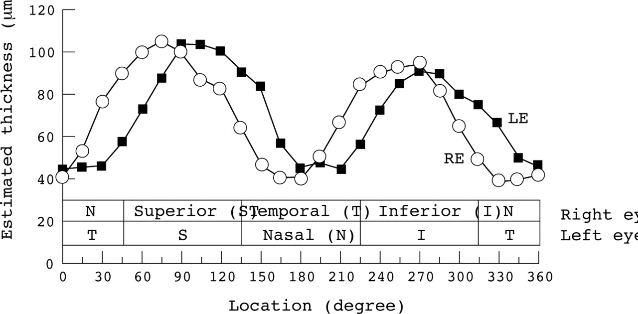
Condition 4: Swapped eye position
The double humped pattern of RNFLT was shifted about 30 degrees anticlockwise (Fig 2). The changes between the baseline measurements and the measurements with the opposite eye position were statistically significant (p<0.0001, Scheffe multiple comparison test, Table 1).

The measurement at the opposite eye position. The NFA decides the right eye is the left eye by measuring the position of the head rest. The peak points of the retardation maps were shifted about 30 degrees anticlockwise.
Study 2: Measurements with an artificial nerve fibre layer
MATERIALS AND METHODS
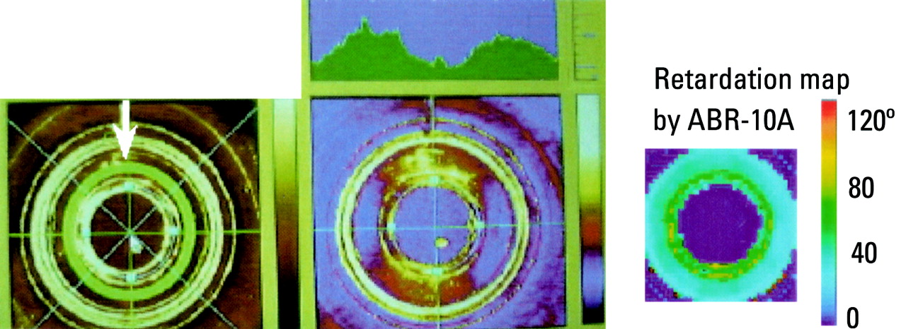
To confirm the RNFLT measurement, we designed a simulation of the artificial nerve fibre layer measurement without a cornea. The birefringence measurements were confirmed with a plastic disc, which has a radial arrangement of birefringence. Generally, a plastic plate has birefringence property due to a molecular arrangement which is formed in the process of solidification from the liquid state. We used the central transparent area of the CD-R disc XCD-R74V (Onkyo Co, Ltd, Japan). The arrangement of birefringence and the retardation value of the plastic plate were checked with an automatic birefringence evaluation system (ABR-10A, Uniopt Co, Ltd, Shizuoka).16
The plastic disc with black paper was fixed at the right eye position or the left eye position on the head rest. The plastic plate and black paper were fixed 15 cm from the lens of the NFA. The plastic plate was set perpendicularly to the laser beam. The laser beam from the NFA passed through the plastic plate, was reflected back by the black paper, and so it passed through the plastic plate twice. The NFA detected the retardation of the returned laser beam from the plastic disc which was an estimate of this artificial “RNFLT”. The illumination setting of the laser beam was the same for all measurements. The RNFLT was evaluated within a 5 pixel wide band located in the subject area of the CD-R disc concentrically. The mean thickness in each of the 15 degree sections (24 sections in 360 degrees) were plotted in Figure 3.

The retardation map of the artificial nerve fibre layer using two devices. The left image shows a subject area with a ring (arrow) in the photographic image. The right image shows the retardation map of the plastic plate by the ABR-10A. The uniformity of the retardation on the subject area was confirmed. The centre image shows the retardation map with profiles by the NFA. The double humped pattern was observed.
RESULTS
The retardation maps of the plastic disc are shown in Figure 3. The retardation profile of the plastic disc was a flat pattern using the ABR-10A, but it was a double humped pattern with the NFA. The mean thickness of the thickest section and the thinnest section with the NFA were 105.2 μm and 39.4 μm, respectively (Fig 4).
The estimated NFLT of the artificial nerve fibre layer. This graph plots the NFLT value in right eye position and the NFLT value in left eye position. In spite of uniform retardation, the thickest section and the thinnest section were 105.2 μm and 39.4 μm, respectively.
The peak points of the thickness on the NFA were different between the right eye position measurement and the left eye position measurement (Fig 4).
Discussion
In study 1, we confirmed the properties of scanning laser polarimetry. The NFA has a high reproducibility of measurement. However, the measurement was affected by the rotation of the eye. This rotation was created by shifting the head significantly. This phenomenon was not the result of the change of the illumination setting or the offset of the laser beam because these effects are not significant in study 1. From this result, the reader might misunderstand that the NFA has a property in which the proportion of the NFLT results in same pattern in any eye. However, the cornea has a radial arrangement of birefringence. The manufacturer recommended taking an image with an undilated pupil and justifying the target ring to pupil, because the centre of cornea has uniform birefringence.17 Even through the central cornea, the NFA needs corneal compensation. To confirm the amount of compensation, we measured the artificial NFLT without the cornea in study 2. We expected to get a flat profile. But the profile of retardation was a double humped pattern. The thickest part and the thinnest part are 105.2 μm and 39.4 μm, respectively (Fig 4). The difference between this double humped pattern and flat profile is thought to be the amount of compensation because the ABR-10A does not have a corneal compensator. It was not a small value compared with the RNFLT. The NFA has a filter, the corneal compensator, which has a certain birefringence for compensating the cornea and fixed its axis +15 degrees or −15 degrees shifted for right eye or left eye respectively (confirmed by oral communication with Dr Dreher; Laser Diagnostic Technologies, Inc, May 1999). We observed this rotation of the compensator through the lens of the NFA. The difference between the right eye and the left eye in Figure 4 was consistent with the rotation of the compensator. Therefore, the measurement on the opposite eye position had a 30 degree shifted incorrect corneal compensation. The significant change of the swapped eye position was explain by this incorrect corneal compensation.
The measurement with the 90 degree rotated eye has a similar double humped pattern to the baseline measurement. However, the thickness of the thickest point was thicker than one of the base line measurements. This may be caused by an uncompensated cornea and nerve fibre layer. It means the total retardation by the cornea and the NFL were larger in the horizontal than in the vertical meridian. If the NFLT of the temporal side of the optic disc was not thicker than that of the superior or the inferior side, the increasing thickness of the thickest point in the 90 degree rotated eye was due to the corneal birefringence. Therefore, it may be difficult to use the image of the 90 degree rotated eye for glaucoma diagnosis, because it includes a lot of corneal birefringence. The most important question is if the corneal compensator is adequate or not.
We reported that the NFLTs above and below the optic disc measured with the NFA were correlated with visual field change, but not on the temporal side of optic disc.13 In another report, using the NFA, we reported that the NFLT of the temporal side was not different between the severe glaucoma eyes and age matched normal controls.18 This result shows that the NFLT of the temporal side of the optic disc will not even diagnose severe glaucoma correctly. A histological study,14 which compares the NFLT by NFA and by a histological measurement, agrees with this result. These findings support the conclusion that the corneal compensation for the temporal side of optic disc is not adequate.
In spite of the fixed corneal compensator, the NFA did achieve good sensitivity and specificity for glaucoma diagnosis.12 13Therefore, we believe that scanning laser polarimetry has potential. However, the validity of measurements by the NFA on the nasal and temporal side are diminished by incorrect corneal compensation. To increase the diagnosing ability, we expect some improvement in this technology. One of the most hoped for reforms is a new compensation method based on individual corneal birefringence. However, measurement of corneal birefringence is a problem. Generally, birefringence has information about the retardation and the orientation of the principal axis. But the NFA is using only the information about retardation and not the information about the axis. The second option for improvement is thought to be a new evaluation method of birefringence including the information on the axis. This study on scanning laser polarimetry is just a start. We hope scanning laser polarimetry will improve its diagnostic ability and so be used more often clinically.
Acknowledgments
This work was reported at the 9th Meeting of the Japan Glaucoma Society, Tokorozawa, Japan. 11 September 1998 (study 1) and the annual meeting of the Association for Research in Vision and Ophthalmology, Fort Lauderdale, USA, 9 May 1999 (studies 1 and 2).