Article Text

Abstract
Aims: To describe the optics of in vivo confocal microscopy, its advantages over previous methods, and to summarise the literature that arose from its use for the observation of the human cornea. A critical review of the clinical usefulness of this new technology for the corneal examination is undertaken.
Methods: Confocal microscopes obtain increased resolution by limiting the illumination and observation systems to a single point. Rapid scanning is used to reconstruct a full field of view and allows for “real time” viewing.
Results: Coronal sections of the in situ epithelium, Bowman’s membrane, stroma, and endothelium can be visualised at a resolution of 1–2 μm. A backscattered light intensity curve allows objective measurements of sublayer thickness and corneal haze to be taken. In vivo confocal microscopy is therefore particularly useful in the areas of infective keratitis, corneal dystrophies, refractive surgery, and contact lens wear, where it aids in differential diagnosis and detection of subtle short and long term changes. Real time endothelial cell assessment can also be performed.
Conclusion: Because of their ability to visualise living tissue at cellular levels, confocal microscopes have proved useful additions to the current clinical tools.
- confocal microscopy
- cornea
- refractive surgery
- keratitis
- contact lens wear
- CMTF, confocal microscopy through focusing
- CORs, coefficients of repeatability
- LASEK, laser epithelial keratomileusis
- LASIK, laser in situ keratomileusis
- PRK, photorefractive keratectomy
- SSCM, slit scanning confocal microscope
- TSCM, tandem scanning confocal microscope
Statistics from Altmetric.com
- confocal microscopy
- cornea
- refractive surgery
- keratitis
- contact lens wear
- CMTF, confocal microscopy through focusing
- CORs, coefficients of repeatability
- LASEK, laser epithelial keratomileusis
- LASIK, laser in situ keratomileusis
- PRK, photorefractive keratectomy
- SSCM, slit scanning confocal microscope
- TSCM, tandem scanning confocal microscope
Microscopic evaluation of the ocular structures has always been a challenge for ophthalmic clinicians and researchers. Although the inherent transparency of the cornea was exploited initially in instruments such as the slit lamp biomicroscope and the ophthalmoscope, detailed, in vivo, high magnification ocular observations still presented many difficulties. Therefore, microscopic anatomical and physiological studies have, until recently, been limited to in vitro investigations. These are prone to introduce many artefacts and do not permit sequential images of evolving disease processes. Clinical confocal microscopy was developed to overcome some of the limitations of conventional light and electron microscopy such as the need to fix and process samples before evaluation. In the late 1980s, technological advances led to the development of powerful clinical confocal microscopes that allow observations of the living human eye in situ at the cellular level. Previous reviews provide a useful introduction to the historical development and some of the applications of confocal microscopy.1–6 The purpose of this review is to present the underlying optical principles that make confocal microscopy such a powerful tool and to provide an up to date critical summary of the increasingly abundant literature arising from its use in the normal and abnormal human cornea.
THE INSTRUMENT
A major limiting factor of conventional light microscopy is that light reflected from structures surrounding the point of observation obscures the image. This produces fringing effects and reduces the resulting image contrast. As a result, useful magnifications in ophthalmic instruments such as the slit lamp biomicroscope are limited to about 40 times, or a resolution of approximately 20 μm. Increasing magnification would only produce bigger blurry images. Observation of the cornea is also made difficult by the fact that it is an almost transparent tissue that only reflects about 1% of the incident light. The principle of confocal microscopy was first described by Minsky in 1957.7 He proposed that both the illumination (condenser) and observation (objective) systems be focused on a single point (have common focal points), hence the name “confocal” microscopy (Fig 1).7 This dramatically improved the axial (z) and lateral (x,y) resolution of microscopy by eliminating out of focus information, bringing lateral resolution to an order of 1–2 μm and axial resolution to 5–10 μm. This allows for possible magnification of up to 600 times, depending on the numerical aperture of the objective lens used.

Diagrammatic representation of the optical principles of confocal microscopy. White light that passes through the first pinhole is focused on the focal plane in the cornea by the condensing lens. Returning light is diverted through the objective lens and a conjugate exit pinhole and reaches the observer or camera. Scattered out of focus light from below or above the focal plane (broken lines) is greatly limited by the pinholes and does not reach the observation system.
Because of the very limited field of view provided by these confocal imaging systems, it is necessary to rapidly scan the focal point across the sample and reconstruct the image to allow a real time on-screen view. Tandem scanning confocal microscopes (TSCM) use rotating Nipkow disc technology.8 A Nipkow disc consists of a metal plate with a series of microscopic holes arranged in an archimedian spiral. The pinholes provide multiple single spot illumination and rapid disc rotation allows scanning of the whole specimen. Slit scanning confocal microscopes (SSCM) use conjugate rapid scanning thin optical slits.9 While these are truly confocal in one axis only, they can offer reduced scanning time and increased light output compared to the TSCM. The light source in clinical confocal microscopes therefore consists of either a small spot or a narrow slit. Because of the risk of phototoxicity involved with the use of coherent laser beams, incoherent white light, in association with ultraviolet and infrared filters, is preferred for clinical instruments.
Involuntary movements due to pulse, respiration, and ocular microsaccades remain a major limiting factor for the use of these systems in vivo, necessitating rapid image capture systems (video and/or digital) with exposure time per frame of less than 1/30 second in order to avoid blurring of the images captured.
Contrary to conventional light microscopes where transverse sections are the norm, confocal microscopy provides a coronal optical section through the human eye. The focal plane of the objective is controlled either manually or automatically through computerised motors. By recording the movement of the objective between images, corneal depth can be assessed for each image. Water immersion objectives of high numerical apertures are typically used as they eliminate surface reflections and provide good depth resolution. Unfortunately, high numerical aperture objectives currently require short working distances and this limits the depth of tissue penetration possible. Subject preparation will therefore often include the use of topical anaesthetic, as this will improve the potential discomfort caused by the short working distance, bright illumination, and use of coupling agents.
Current instruments provide resolutions sufficient for the visualisation and detection of corneal cells; however, internal cellular structures (mitochondria, vacuoles, and other organelles) cannot be resolved. The development of higher numerical aperture objectives with longer working distances and coherent laser light sources safe for use in vivo are some of the avenues where advances are likely in coming years.
THE NORMAL CENTRAL CORNEA
Using specular microscopy, Maurice first obtained unstained photographic images of a fresh ex vivo rabbit corneal epithelium, stroma, Descemet’s membrane and endothelium at a magnification of approximately 500 times in 1974.10 It is not until the next decade that confocal microscopy was used to visualise optical sections of the corneal surface epithelium, the basal epithelium, Bowman’s layer, the corneal stromal keratocytes and collagen fibres, and the endothelial cell layer of intact non-stained excised human eyes.11–13 The first images obtained from observations of human eyes in situ, using prototype instruments were published soon after.13–16
An SSCM (Confoscan 2, Fortune Technologies, Virgona, Italy) was used to capture the sample images shown in Figure 2. When used in combination with a 40 times, 1.98 mm working distance, 0.75 numerical aperture Achroplan immersion objective, this instrument provides a lateral resolution of 1 μm and a depth of field resolution of 10 μm. Images of an area measuring approximately 340 × 255 μm are digitally captured.

(A) Corneal histology: meridional section of the human anterior (top) and posterior (bottom) cornea, stained with haematoxylin and eosin. Inset = full section. DM = Descemet’s membrane; En = endothelium; K = keratocytes (reproduced by permission of Edward Arnold from Bron AJ, Tripathi RC, Tripathi BJ. Wolff’s Anatomy of The Eye and Orbit, p 235). (B) Schematic representation of the human keratocyte network (reproduced with permission from Hogan MJ, Alvarado JA, Weddell JE. Histology of the Human Eye, p 92). (C-F) In vivo confocal microscopy of the central human cornea. Bar = 50 μm. (C) Surface epithelium cells and their nuclei (arrow). (D) Basal epithelium. (E) Keratocyte nuclei in the anterior stroma. Bright areas may indicate increased metabolic activity. (F) Endothelium. Cell nuclei (arrow) and endothelial guttae (arrowhead) are occasionally visible.
A meridional histology section of a normal human cornea is reproduced in Figure 2A and the corresponding aspect of each coronal confocal microscopy section at various depths is shown in Figure 2C–F. Superficial epithelial cells have light cell boundaries and bright visible nuclei (arrow) (Fig 2C). Smaller basal epithelial cells also have light cell boundaries (Fig 2D). In the stroma, keratocytes are visible as light cell bodies against a dark background (Fig 2E). A diagrammatic representation of the keratocyte network is reproduced in Figure 2B, showing the keratocyte oval nucleus, its surrounding body, and the long interconnected keratocyte processes. It is uncertain which portion of the keratocyte cell is observed under normal conditions with confocal microscopy but comparisons of the in vivo (confocal microscopy) and ex vivo (light microscopy) aspects suggest that only the nucleus, or at best, the nucleus and a small portion of the cell body are visualised.17 Neither the keratocyte processes nor the stromal collagen fibres are visible under normal conditions. The endothelial mosaic appears as light cells with dark borders (Fig 2F) and is comparable in quality to images captured using the specular microscope. An endothelial cell nucleus (arrow) and guttae (arrowhead) are occasionally visible. Descemet’s membrane cannot be visualised in normal young corneas at this resolution.
In addition to the qualitative analysis of corneas imaged with confocal microscopy, quantitative analysis is increasingly used to compare normal and diseased states. A system allowing automated recognition of the specific cell layer in confocal microscopy images has recently been proposed to compensate for difficulties in layer identification due to eye movements.18 Endothelial cell counts can also be performed on confocal microscopy images. When compared to wide field specular microscopy, a considerably smaller number of cells are analysed at the high magnification provided by confocal microscopy. Notwithstanding, both semi-automated19 and automated20 counts have been shown to correlate well with specular microscopy results. Because of its ability to provide real time sequential observations of the whole corneal endothelium, confocal microscopy may very well replace specular microscopy as the method of choice for monitoring endothelial health status in diseased and postoperative corneas.
Endothelial analysis aside, a combination of manual marking and/or cell border tracing with or without prior image processing to enhance visual detection is the norm for cell size and density measurements.21–36 There is conflicting evidence on the reliability and repeatability of manual measurements, particularly when multiple and/or untrained observers are used.22,33,37,38 Measurements performed in the corneal stroma are further complicated by the three dimensional aspects of keratocyte images, necessitating the application of stereological rules for the transformation of measurements performed on a two dimensional confocal microscopy image into their three dimensional equivalent. Theoretically, the use of automated image analysis could provide increased speed, accuracy, and repeatability of cell size and density measurements and attempts have been made to develop automated systems for quantifying the density and/or dimensions of surface epithelial cells39,40 and stromal keratocytes.41–43 To date, automated image analysis systems of the corneal epithelium and stroma are not validated against or show poor agreement with other known in vitro techniques in humans. Studies reporting results obtained using non-validated systems should be interpreted with caution.44
The development and validation of such an image analysis system for quantifying keratocyte volume density is currently under way (Jalbert et al, unpublished data). Using this system, stromal keratocyte volume density (cells/mm3) was assessed as a function of corneal depth in a single human subject (Fig 3). The graph clearly illustrates the previously demonstrated decrease in keratocyte density from the anterior to the posterior stroma in humans.28 Using confocal microscopy, other significant associations have been demonstrated in the normal corneal stroma in vivo such as a decrease in keratocyte density with age (5% per decade) and a negative correlation between keratocyte density and stromal and total thickness.28 Such findings provide useful insights into the normal cornea.

Automated keratocyte volume density (cells/mm3) as a function of the stromal depth (%) in a single human subject. The average density is 4.9 × 10⁴ cells/mm3 for this eye.
The human cornea is richly innervated. The unmyelinated sub-basal nerve plexus is visible on confocal microscopy images at the level of the acellular Bowman’s layer (Fig 4A). Single nerve fibres are beyond the resolution limit of confocal microscopy and only beaded nerve bundles can be observed. In the anterior corneal stroma, larger nerve fibre bundles are easily observed (Fig 4B) and signs of apparent keratocyte-nerve interactions are occasionally noted in the central cornea (Fig 4C). In a landmark publication, Auran and colleagues using sequential confocal microscopy observations of the sub-basal nerve plexus obtained a resolution comparable or even superior to that obtained with histopathological staining.45 This study directly confirmed the “X-Y-Z” hypothesis46 of corneal epithelial cell migration. Furthermore, it demonstrated for the first time axon growth in the basal epithelial nerve plexus, raising the possibility that both basal epithelial nerves and epithelial cells migrate centripetally in tandem. Again, manual counting/measuring can be used to quantify the neural status.36,38,47–51 Automated measurement systems for the corneal nerves have yet to be developed.
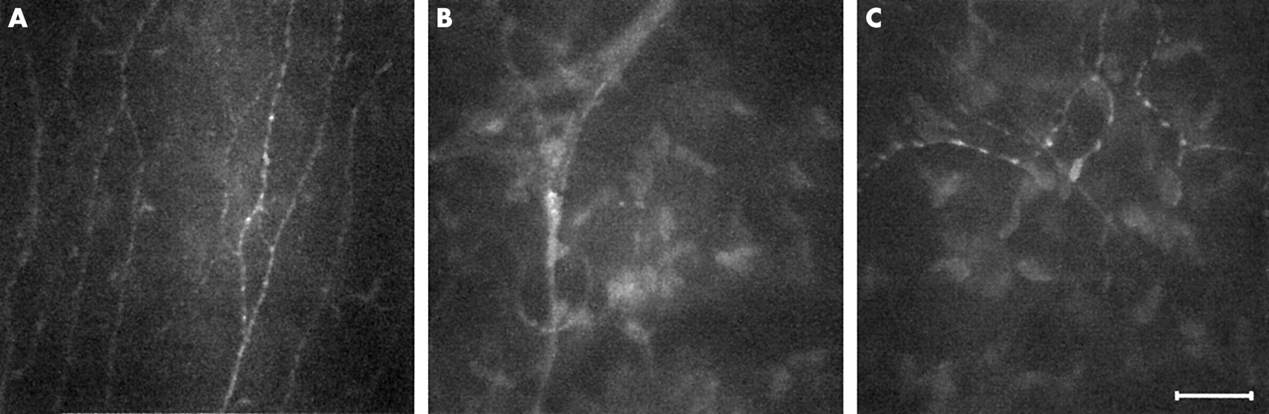
The human corneal innervation. After penetrating Bowman’s layer, large fibres divide into smaller mostly parallel nerve fibre bundles and single nerve fibres. Single fibres travel anteriorly to innervate the corneal epithelium. Confocal microscopy is able to resolve parallel beaded nerve fibre bundles at the sub-basal epithelial level (A). Large nerve fibres enter the cornea in the anterior two thirds of the stromal periphery (B). Smaller nerve fibres appear to sometimes interact with keratocyte nuclei (C). Bar represents 50 μm.
OTHER OCULAR SITES
Using appropriate objectives and modifications to the instrument design, the use of confocal microscopy for the examination of the tear film,52 crystalline lens,53 and retina54 has been demonstrated. Controlling fixation also allows perusal of sites other than the central cornea (Fig 5). Scans of the thicker corneal periphery reveal a structure identical to that of the central cornea,28 however, antigen presenting Langerhan’s cells can occasionally be observed at the level of the sub-basal nerve plexus (Fig 5A). Furthermore, the conjunctival epithelium (Fig 5B) and stroma (Fig 5C) may also be observed in some detail.

By controlling subject fixation, confocal microscopy may be performed outside the central cornea. (A) Langerhan’s cells (arrows) are sometimes seen along a thin sub-basal nerve bundle near the cornea limbus. (B) The epithelium of the normal conjunctiva is brightly reflective while the conjunctival stroma (C) appears to be mostly acellular and less transparent than the corneal stroma. Bar represents 50 μm.
THICKNESS AND CORNEAL TRANSPARENCY MEASUREMENTS
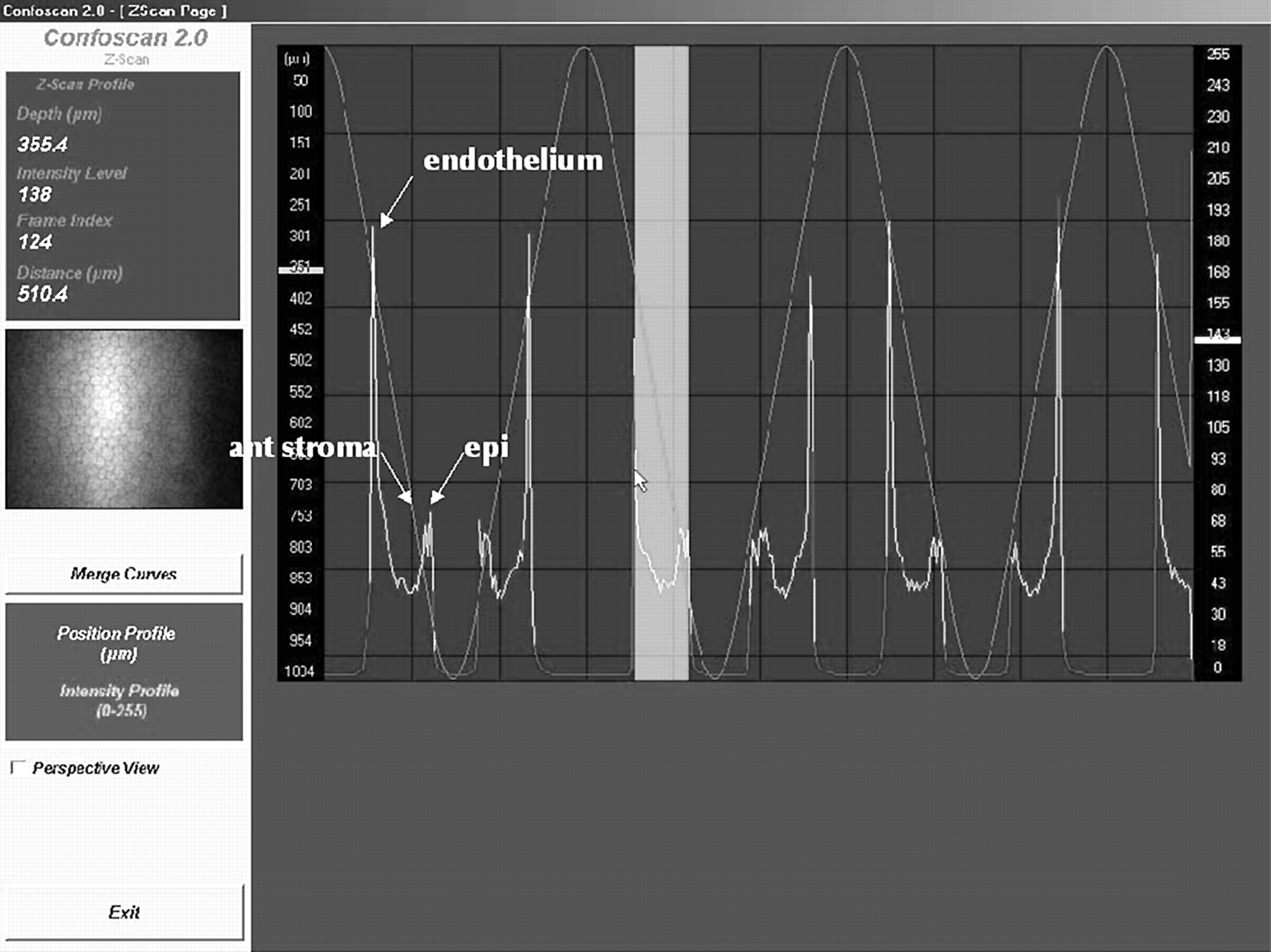
Confocal microscopes can be used to measure corneal thickness.28,42,55,56 This function is called confocal microscopy through focusing (CMTF) on the TSCM.55 Briefly, rapid movement of the objective lens itself 42,56 or of the focus of the objective lens28,55 in the Z-axis is automated and registered by a computer. The amount of light backscattered by the central section of each image is also recorded, allowing the generation of an intensity profile curve (Fig 6). Specialised software allows interactive viewing of the image corresponding to the cursor location on the Z-curve and measurement of the distance between any two points on the curve. Because different layers of the cornea reflect light at different intensities, the depth-intensity profile allows for the determination of corneal sublayer location. As well as corneal thickness, measurements of epithelial thickness, Bowman’s layer thickness, and following laser in situ keratomileusis (LASIK) surgery, flap thickness can also be obtained.55,57

The Z-scan function on the Confoscan 2 slit scanning confocal microscope. The amount of backscattered light is plotted in intensity units (0 to 255) on the right hand side scale for each consecutive image (X axis). The corresponding relative depth is also shown on the left side scale in μm. High peaks correspond to the corneal endothelium, lower peaks to the most anterior keratocyte layer and the corneal epithelium (epi). The image corresponding to the cursor location (in this example, the corneal endothelium) is interactively displayed on the left panel. Corneal thickness (arrow) is assessed by measuring the distance travelled by the microscope head between peaks corresponding to the corneal endothelium and the corneal epithelium, 510.4 μm in the example shown here.
The precision of various techniques for the in vivo measurement of corneal thickness is best compared using coefficients of repeatability (CORs) (Table 1). These CORs are derived by multiplying the within subject standard deviation by the appropriate t value. While techniques such as modified optical pachymetry,56 optical low coherence reflectometry,58 and its three dimensional manifestation, optical coherence tomography,59–61 demonstrate best precision, the CMTF function of the TSCM offers moderate to good repeatability, particularly for measurements of thin layers such as epithelial or Bowman’s layer thickness.55 SSCM has been reported to be poorly repeatable for thickness measurements56; however, this experiment was conducted using an image separation of approximately 25 μm. Reducing this image separation to a minimum may improve repeatability but until confirmed, SSCM thickness measurements should be supplemented with another technique. The use of a low vacuum suction cup is said to improve the precision of pachymetry measurements with the SSCM; however, insufficient data are available for CORs to be calculated.42 Similarly, the repeatability of another novel in vivo measurement technique using high frequency ultrasound, although promising, is difficult to accurately assess based on the data available and may be limited in its application because of the necessity for coupling immersion of the cornea.62 Future improvements in image capture speed, stabilisation methods, and/or sampling rate63 will no doubt increase the applicability of confocal microscopy measurements of thickness. Finally, the accuracy of CMTF measurements is difficult to assess from the literature. Good agreement between ultrasonic pachymetry, the gold standard pachymetric method, and CMTF measurements of total corneal thickness in rabbits suggests that these two techniques can be interchanged; however, more recent data in humans demonstrated poor agreement between CMTF and ultrasound pachymetry, the latter apparently overestimating corneal thickness.64
Intrasession coefficients of repeatability (CORs) of in vivo methods for the measurement of central corneal thickness in humans
Single sections from oblique confocal microscopy scans on humans wearing a soft contact lens of known thickness can be used for measuring the thickness of the anterior corneal layers.65,66 While not affected by subject movements like CMTF, the precision of measurements with this technique will vary with contact lens hydration, post-lens tear film thickness and observation angle. The accuracy and repeatability of the method has not been reported to date. The technique is infrequently used now owing to the limitations of being applicable to anterior corneal layers only and has been practically superseded by other methods.
In addition to thickness measurements, the z-curve provides an objective measure of corneal transparency. The amount of backscattered light given in intensity units or in intensity thickness units can be used to assess and monitor the relative transparency of the corneal stroma and provides an estimate of corneal haze.32,67–70 Other methods previously available for the in vivo objective measurement of corneal transparency include Scheimpflug photography,71,72 slit lamp photometry or scatterometry,73 74 charge coupled device (CCD) camera systems,75,76 and opacity lensometers.77 All of these methods exclusively measure light scattered or reflected back towards the observation system. Forward scattered light, which is more likely to affect retinal image quality and visual acuity measurements, is best measured using the Van den Berg stray light meter.78 Limited information is available on the repeatability and accuracy of objective haze measurement techniques and no comparative studies have been undertaken to date. The opacity lensometer was reported as poorly discriminating for the low haze or high corneal transparency range of values.77 High intrasession and day to day coefficients of variation of 4% and 7%, respectively have been quoted for slit lamp photometry measurements.73 An equally good coefficient of variation of 3.5% is reported for repeated measurements using a CCD system in a single rabbit.76 In comparison, the repeatability of corneal transparency or corneal haze estimates using confocal microscopy are moderate with average coefficients of variation reaching 35%70 and intrasession CORs reaching 8.2 intensity units.56 Confocal microscopy and Scheimpflug photography remain the methods of choice because of their capacity for sublayer haze measurements, allowing for localisation and characterisation of scarring or haze.
THE ABNORMAL HUMAN EYE
Because of the many advantages confocal microscopy provides such as the visualisation of structures through oedematous corneas and the ability to perform high resolution real time sequential in vivo observations, it is increasingly used for the examination of the abnormal human eye. It has been successfully applied in two major areas: the in vivo characterisation of corneal degeneration and dystrophies and the differential diagnosis of keratitis and keratopathies.
The list of corneal degenerations and dystrophies studied with in vivo confocal microscopy is extensive and includes epithelial basement membrane,79–82 Reis-Bücklers’,83,84 Meesmann’s,79,80 lattice,48,84–87 fleck,80,88,89 granular,80,83,84 Schnyder crystalline,32,90 and posterior polymorphous85,91,92 dystrophies, Fuchs’ endothelial dystrophy and/or cornea guttata,19,79,80,93–95 autosomal recessive cornea plana,96 keratoconus,95,97 iridocorneal endothelial syndrome,83,95,98 Salzmann’s nodular degeneration,82,99 retrocorneal membrane,100,101 and rare primary102 corneal amyloidosis. Corneal dystrophies and degenerations are typically rare, thus the availability of corneal tissue for examination of the disease at the microscopic level has previously been limited, particularly in the early disease stage. In vivo confocal microscopy provides a major advantage as it permits in situ characterisation of these dystrophies and their progression. In addition, the z-scan curve can be used to assess the level and location of corneal haze associated with the various corneal dystrophies. This function was recently used in a case of phototherapeutic keratectomy of a Schnyder’s central crystalline dystrophy to demonstrate significant reduction of corneal haze.32
Confocal microscopy may therefore lead to earlier diagnosis and has, for example, already been shown to be useful in rectifying misdiagnosis in cases of Fuchs’ endothelial dystrophy93 and iridocorneal endothelial syndrome95 wrongly diagnosed as herpetic keratitis. It has also been used to monitor the effectiveness of amniotic membrane grafting in a case series of severe corneal degeneration.103 Figure 7 illustrates the enhanced detection and resolution available with confocal microscopy when compared to the traditional slit lamp biomicroscopy appearance of corneal dystrophies.

Confocal microscopy of corneal dystrophies. (A, B) Epithelial basement membrane dystrophy: a sharp edge abnormality (A) observed at the level of the basal epithelium is caused by basement membrane thickening. The associated nerve plexus (B) displays a markedly reduced density of long nerve fibres and the presence of abnormal short nerve fibres. (C) In an early case of keratoconus, activation of the anterior-most layer of the stroma is evidenced by the increased reflectivity of the keratocyte nuclei and the hazy extracellular matrix. (D) Clumps of brightly reflective microdot deposits in the posterior-most layer of the stroma are observed in a case of Fleck dystrophy. (E, F) Fuchs’ dystrophy is characterised in the moderate stage by microbullae in the basal epithelium (E) and some endothelial guttae (F). Bar represents 50 μm.
The rapid and accurate diagnosis of sight threatening infective keratitis is a major challenge for ophthalmic practitioners when delays in appropriate treatment may adversely affect outcomes. The usefulness of confocal microscopy in cases of keratitis was demonstrated early on in corneas infected with acanthamoeba.83 Features such as double walled cysts in acanthamoeba keratitis104,105 and fungal hyphae in keratomycosis85,106,107 are easily identifiable with the current resolution of the confocal microscope. It is however often difficult to discriminate between different cellular components such as host inflammatory cells and smaller infecting micro-organisms in confocal microscopy images. Most offending micro-organisms in microbial keratitis are around 1–3 μm in size. They can be visualised, but as they approach the present resolution limits of confocal microscopy, they are often impossible to identify by bacterial morphology alone,108,109 unless they present with distinctive features such as the intracellular spores in a case of microsporidial keratitis.110 Adjunct techniques such as scrapings, biopsies, and DNA analysis are still often required to confirm diagnosis.110,111 Nevertheless, confocal microscopy is extremely useful in diagnosing atypical keratitides where large extracellular infecting organisms are present such as acanthamoeba (Fig 8),83,104,105,111–115 fungal,85,106,107,116 and lyme borrelia117 keratitis. A recent observation of frequent presumed Langerhan’s cells in post herpetic keratitis corneas may further enhance the usefulness of confocal microscopy in differentially diagnosing keratitides.51 Interestingly, the use of confocal microscopy in all suspected keratitis cases in a major teaching hospital coincided with an apparent epidemic of acanthamoeba keratitis.104,111,118 This is probably the result of increased sensitivity of confocal microscopy for the detection of mild acanthamoeba cases and may not necessarily reflect a real change in the epidemiology of the disease. Other keratitides also characterised using confocal microscopy include herpetic,51,83 and Thygeson’s119 keratitis, toxic29,120–124 and neurotrophic125 keratopathy, and advancing wavelike epitheliopathy.126 As well as being a diagnostic tool, confocal microscopy has been used for monitoring the effectiveness of the treatment of keratitis—for example, the eradication of infecting agents leading to timely administration of corticosteroids and/or tapering of often highly toxic antifungal or antiprotozoal agents.107,113,127 It can also be used to characterise the scarring caused by various keratitides.128
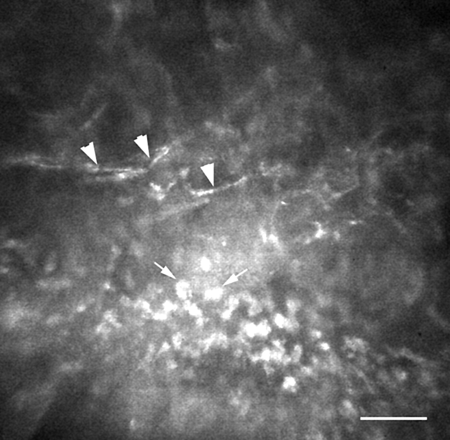
This slightly oblique corneal section displays the basal epithelium (bottom) through to the anterior stroma (top) of the leading edge of the ulcer in a suspected case of acanthamoeba keratitis. Brightly reflective round structures at the basal epithelial level (arrows) are characteristic for necrotic epithelium. Abnormal nerves with localised inflammation (arrowheads) are also observed. Bar represents 50 μm.
Confocal microscopy has also been used to characterise corneal alterations associated with a variety of systemic and/or ocular diseases such as diabetes,47,129,130 Marfan syndrome,131 glaucomatous megalocornea,132 and chronic uveitis.133 In these case series, confocal microscopy is often able to detect subtle corneal changes that precede other more commonly known detectable impairments.47,133
EFFECTS OF REFRACTIVE CORRECTION
Given the increasing popularity of refractive surgery procedures, understanding, controlling, and modulating the corneal wound healing response is of primary concern. This is perhaps the area where confocal microscopy may be most advantageous as it can be used to characterise cellular changes associated with the wound healing response and its variability in humans prospectively. For the first time, changes in the appearance of the corneal stroma, keratocytes, and corneal nerves can be visualised over time at high resolution. Sublayer thickness can also be measured, allowing for in vivo monitoring of subepithelial haze depth and possible tissue rethickening (regression) after excimer laser photorefractive keratectomy (PRK) and measurement of flap thickness following LASIK. In addition, recording the amounts of backscattered light can also provide an objective measurement of the corneal haze associated with the wound healing response.
Confocal microscopy has therefore been used extensively to study human corneas undergoing PRK.50,65,70,127,134–143 The short term wound healing processes previously described in animals using histological methods are mostly confirmed by confocal microscopy examinations. Briefly, regenerating epithelium quickly covers the wound,65,70,134,142 the anterior stromal keratocytes become highly reflective, hypertrophic, and hyperplastic,50,65,70,127,134,139–142 the nerve plexus slowly regenerates from the wound edge to the central cornea by sprouting of nerve fibres,50,70,127,134,135,137,140,141 and a layer of subepithelial scar tissue is deposited at the epithelial-stromal interface.50,65,70,127,134,141
Interestingly, the apoptosis mediated initial keratocyte density reduction observed in PRK animal models144 has so far not been convincingly demonstrated in prospective human studies using confocal microscopy post-PRK. However, it may be that the highly reflective subepithelial scar tissue layer obscures zones of potential acellularity. More importantly, confocal microscopy demonstrated unequivocally that PRK always produces long term changes, even in corneas clinically termed to have “zero haze.” These changes range from occasional highly reflective basal cells,136,138 abnormal branching of the sub-basal nerve plexus,135–138 a fine subepithelial scar layer,127,136,138 as well as to the observation of “rod” and “needle” shaped highly reflective stromal structures.127,136,138
Using confocal microscopy, corneal haze can also be measured both quantitatively and objectively.50,70,140,142 Møller-Pedersen and colleagues were first to use CMTF to demonstrate that PRK creates a measurable subepithelial haze peak on the backscattered light reflectivity curve. The area under the curve generated by this peak (in μm per pixel intensity) provided a valid haze estimate that correlated well with clinical haze gradings.70 Recent evidence gathered using CMTF further suggests that the haze originates predominantly from highly reflective wound healing keratocytes rather than from extracellular matrix deposition.140 A significant relation between the density of the regenerating nerve plexus and the epithelial thickness after PRK was also recently demonstrated.50 Such important clues to the dynamics of wound healing in humans have only become available through the use of in vivo confocal microscopy.
LASIK has gained in popularity over PRK because it offers decreased pain, faster recovery, and minimal haze and regression. A number of in vivo confocal microscopy studies of LASIK wound healing have been conducted.31,35,57,67,69,137,143,145–149 In LASIK, the wound healing cascade of events studied in animals with histological methods appear identical to that of PRK and can be visualised using confocal microscopy.31,57,67,69,137,145 One of the differences between the two methods is the location and extent of the initial epithelial injury, which is much greater in PRK than in LASIK where most of the epithelium is preserved intact in the flap. Because close interaction between epithelial and stromal cells is present only at the flap margin in LASIK, the healing response appears somewhat subdued at the flap interface. Flap depth and alignment146 is easily visualised using confocal microscopy as highly reflective particles appear to be deposited at the interface of almost all corneas (Fig 9A).31,35,57,67,69,147–149 Some activation of keratocytes and extracellular matrix (scar) deposition is observed below and/or above the flap.31,35,57,147 As a consequence, an extra haze peak is often easily detected in the backscattered light curve (Fig 9D).31,57,69,147 Bowman’s layer microfolds are observed in most corneas (Fig 9B).31,35,57,147 Interestingly, the presence of an acellular zone on both sides of the lamellar cut a week after LASIK surgery has been recently reported.31,147 This new evidence supports an apoptosis mediated keratocyte density reduction in the initial stages of the wound healing response. Keratocyte densities appear most affected (reduced) in the stromal layers immediately adjacent to the lamellar cut and changes have been shown to persist for over a year after surgery.35 Furthermore, preliminary observations of increases in epithelial thickness after LASIK surgery suggest epithelial hyperplasia as a mechanism for regression of refractive error correction in LASIK.148,149

Laser surgery. (A) The flap interface after LASIK surgery is evidenced by the presence of brightly reflective particles. (B) Bowman’s layer microfolds (arrows) are observed in most corneas after LASIK. (C) Complications such as epithelial ingrowth (arrow) are easily observed using confocal microscopy. (D) The additional haze peak (arrow) at the level of the anterior stroma in the backscattered light curve can be attributed to residual keratocyte activation 6 weeks after LASIK surgery. Bar represents 50 μm.
The subepithelial nerve plexus preserved in the flap completely degenerates145 before slowly regenerating in a fashion similar to that observed during PRK.35,137,145,149 A sub-basal peak in the backscattered light reflectivity curve can sometimes be observed even in the absence of a nerve plexus.149 Confocal microscopy has also been used increasingly to study complications of LASIK surgery (Fig 9C).150–158 There is, to date, no definitive study on the long term effects of LASIK; however, it is expected that as in PRK subtle changes may be observed in LASIK corneas studied using confocal microscopy.
Confocal microscopy can also be used to characterise and compare the wound healing response in novel refractive surgery techniques as advances and improvements are suggested. For example, it was recently used to demonstrate that laser scrape epithelial removal did not significantly alter the wound healing response in eyes undergoing PRK.142 Confocal microscopy after intrastromal corneal ring segment implantation has also been reported in a single cross sectional case series.159 Laser epithelial keratomileusis (LASEK)160 is a novel technique where a thin epithelial flap followed by alcohol bath, epithelial debridement, and traditional PRK are performed. This new technique is said to combine the advantages of PRK and LASIK, therefore offering less flap or interface related problems with limited postoperative pain and corneal haze.160 The use of confocal microscopy in such cases will be able to objectively confirm or refute this suggested dampening of the wound healing response compared to PRK and preliminary reports are already emerging.143
Confocal microscopy has also been shown to be useful in follow up of penetrating keratoplasty and phototherapeutic keratectomy cases.32,116,134,161–165 As in refractive surgery, corneal haze formation, corneal nerve regrowth, keratocyte repopulating, and endothelial cell counts can be monitored.
Contact lens wear is another very popular method of correcting refractive error that potentially can affect the cornea in a myriad of ways. These are summarised in a number of good reviews.166–168 Confocal microscopy has been used to confirm the following known acute and chronic contact lens induced phenomenon: increased surface epithelial cell size,26,30,34 epithelial thinning,26,30,34 stromal folds,169 endothelial blebs,23 and endothelial polymegethism.68,136 For the first time, the use of confocal microscopy has allowed discrimination of the effects of various lens types worn on an extended wear basis. For example, superficial cell size increase is higher with high oxygen transmissibility rigid gas permeable lenses than any soft lenses (high or low oxygen transmissibility) and epithelial thinning effects follow the hierarchy: high oxygen transmissibility rigid gas permeable > low oxygen transmissibility hydrogel > high oxygen transmissibility silicone hydrogel.26 In some cases, differences between lens types were evident after as little as 1 month of daily wear.30 It remains unclear, however, how duration of wear (more than 1 year) may modulate some of these findings and which, if any, of these changes are reversible.
Soft contact lens wear also significantly alters the thickness of the stroma causing chronic low grade oedema and long term stromal thinning.166 This oedema is probably responsible for the overall increase in the light scattering properties of the cornea of contact lens wearers, observed by the confocal microscopy backscattered light curve.68 For the first time, changes to the cellular structure of the stroma of contact lens wearers can also be detected in vivo. After short term (20 minutes) soft lens wear, hyperreflective keratocyte nuclei have been noted throughout the whole corneal thickness.23 There is anecdotal or preliminary evidence for keratocyte degeneration following low oxygen permeability soft lens wear for 126 and 6 months.170 Long term lens wear (more than 5 years) has also been associated with the presence of stromal microdot deposits127,136,138,171,172 (Fig 10E) with these being more pronounced in the stroma of low oxygen transmissibility soft than rigid gas permeable contact lens wearers.171 An apparent reduction in keratocyte density has also been described in long term soft lens wearers.172 A recent publication challenges some of the above findings reporting no changes in either central epithelial thickness or keratocyte density after more than 10 years of daily contact lens wear.36 In addition, the presence of chronic residual swelling in contact lens wearers may be a confounding factor169 and this should be controlled in future study designs. Large prospective contact lens wearing studies have without doubt benefited from the addition of confocal microscopy to their examination protocol and will continue to do so in the future.34
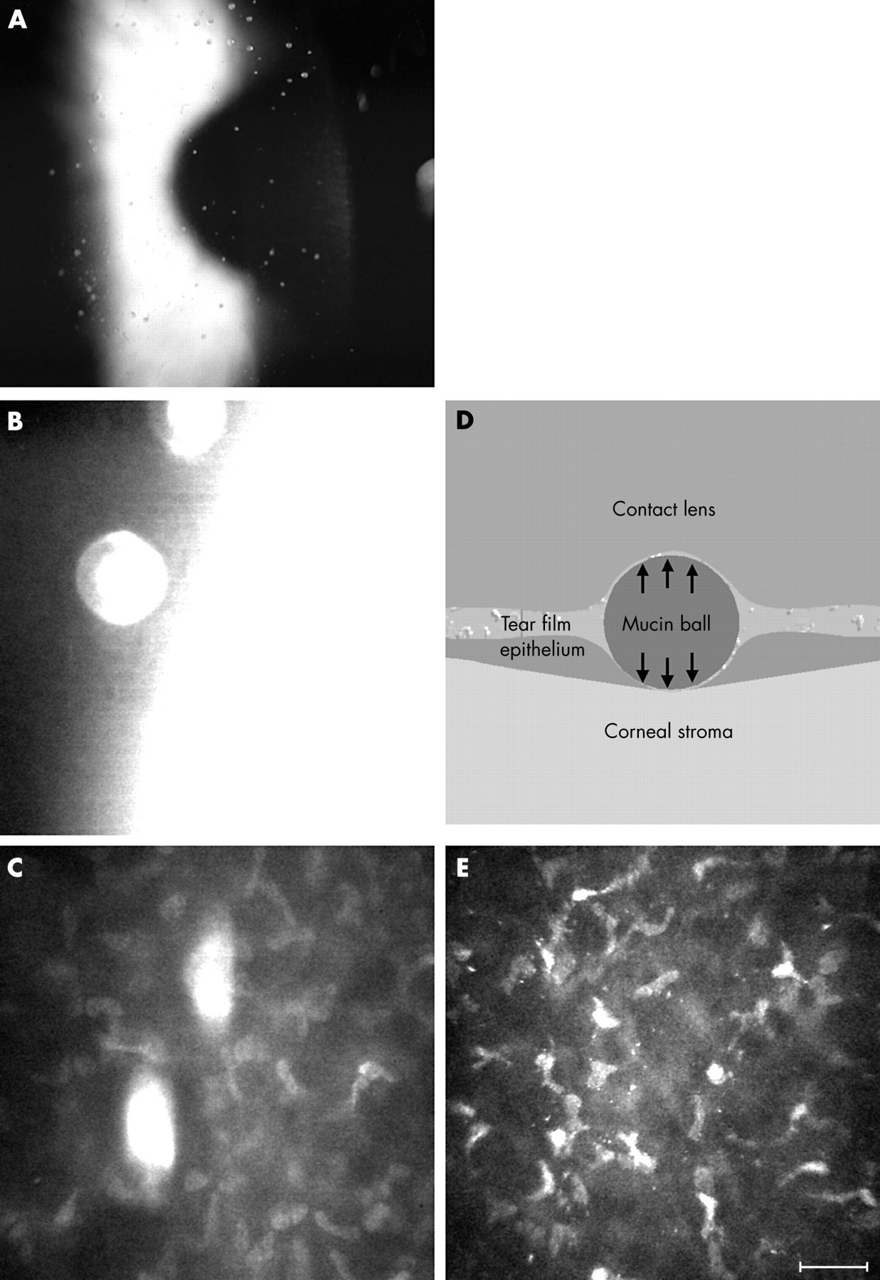
(A) Mucin balls are often observed in wearers of silicone hydrogel lenses with the slit lamp biomicroscope. Confocal microscopy reveals an optically dense round structure (B) that appears to indent both the overlying contact lens and the underlying cornea well below the level of the surrounding Bowman’s layer—that is, within the anterior stroma (C). (D) Schematic diagram of the physical forces (arrows) that may be at play in the presence of a large mucin ball. (E) Stromal microdot deposits in the corneal stroma of a long term (over 15 years) wearer of low oxygen permeability soft contact lenses. Bar represents 50 μm.
When confocal microscopy is performed with a contact lens in place the post-lens tear film can be examined. This ability was used to investigate the nature of mucin balls, a phenomenon that is increasingly described in association with the wear of highly oxygen permeable silicone hydrogel lenses.173,174 Mucin balls appear as small round translucent or opalescent precorneal deposits when observed with a slit lamp biomicroscope (Fig 10A). High magnification in situ observation of large mucin balls is illustrated for the first time using confocal microscopy (Fig 10B, C). Interestingly, confocal microscopy observations of multiple spherical indentations of the corneal epithelium in silicone hydrogel extended wearers have also recently been described and attributed to mucin balls.177
CONCLUSION
Confocal microscopy allows ophthalmic clinicians and researchers to visualise living tissues at greatly increased resolutions. Qualitative observations of the images obtained are rapidly giving way to sophisticated quantitative image analysis systems. So far, confocal microscopy has been used to better characterise the often rare corneal degenerations and dystrophies, as an aid in the differential diagnosis of keratitis and keratopathies, to research the wound healing characteristics of the human cornea following penetrating keratoplasties and refractive surgery procedures, and to study the effects of contact lens wear. Confocal microscopy has also been successfully used in lieu of specular microscopy to obtain endothelial cell counts even in the presence of oedema.
Acknowledgments
Funding was provided in part by the Australian Government through the Cooperative Research Centre Programme and by a Contact Lens Society of Australia 2001 Research Award. Mr Darrin Falk constructed the fixation target used for peripheral scans and Dr Klaus Ehrmann provided valuable technical advice and support. We thank Mr Rob Terry, Mr Simon Kelly, and Dr David Robinson for referral of some of the cases shown in this paper.