Article Text

Abstract
With an ageing population showing an increasing prevalence of glaucoma, there is a pressing demand for continuous intraocular pressure (IOP) measurements which could surpass clinic-based measurements such as routine applanation tonometry. Glaucoma patients have fluctuations in IOP, and it has been proposed that these fluctuations are relevant to glaucoma progression. In addition, interindividual and intraindividual variation in corneal thickness and rigidity can lead to significant and poorly quantitated errors in applanation-based methods of estimating IOP. Microelectrical mechanical systems and complementary metal oxide semiconductor-based technology has enabled the development of smart miniaturised devices by augmenting the computational ability of microelectronics with capabilities of microsensors and microactuators. This review addresses various sensor technologies and both invasive and non-invasive approaches to the measurement of IOP. Advances in wireless communication (telemetry) between the implanted sensors and the external readout device are reviewed. In addition, biocompatibility of implantable sensors is discussed.
Statistics from Altmetric.com
Glaucoma is a heterogeneous disease characterised by pathological retinal ganglion cell loss resulting in loss of visual field and ultimately blindness. Primary open-angle glaucoma (POAG) is one of the most common subgroups and is the leading cause of blindness among African–Americans.1 The main risk factor for POAG is elevated intraocular pressure (IOP), and despite some patients with POAG not having elevated IOP above the normal population range, the only proven therapeutic intervention is IOP reduction.2 All current treatments, whether medical, laser or surgical, primarily act by lowering IOP. Thus, the accurate monitoring of IOP is an essential clinical facet in glaucoma care.
Currently, there are a wide range of modalities available for routine IOP measurement. The most commonly used technique, and current gold standard is applanation tonometry, where the tonometer head directly applanates the cornea. The force required to achieve a fixed degree of applanation provides an approximation of the pressure within the eye resisting this deformation. In addition to requiring topical anaesthetic and a skilled operator, a major disadvantage of applanation tonometry is the interindividual variation in corneal thickness and rigidity which lead to poorly quantitated applanation tonometry errors.3 Additionally, 24 h measurements are difficult to obtain, particularly overnight.4
Remote continuous monitoring of IOP has long been desired by clinicians, and the development of such technology has the prospect of revolutionising glaucoma care. The aim of this review is to summarise the progress made and explore potential future avenues towards automated IOP monitoring. The successful implementation of such a system depends on the sensitivity and accuracy of its sensor, and wireless communication between the implanted sensor and external readout device, which will be discussed in turn. In addition, this review discusses biocompatibility and potential sites for ocular insertion.
STRATEGIES FOR INTRAOCULAR PRESSURE MEASUREMENT
IOP measurement can be classified broadly into two categories, direct and indirect measurements. In the direct (invasive) approach, the sensor is placed inside the eye, providing an accurate representation of the true internal IOP. In the indirect (non-invasive) approach, IOP measurement depends on the assumed knowledge of the relationship between the measured parameter (eg, applanation, or change in corneal radius of curvature) and the true IOP. Clearly, any device aspiring to be used in routine clinical monitoring demands that complications from implantation be minimal, that long-term placement is well tolerated and that accurate measurement is sustained over time.
A number of anatomical options have been explored for device placement, and these are summarised in fig 1. Clearly, the limited space available within the eye is a major limiting factor in implant design. The potential for a monitoring device to be incorporated into existing implants such as contact lenses, intraocular lenses or drainage implants offers an opportunity for dual functionality, but the concept of a device solely for monitoring IOP is not without merit. In the future, but beyond the scope of this review, a device monitoring and actively controlling IOP could be envisaged.

Invasive approaches
Intraocular lens
Cataract surgery and intraocular lens (IOL) insertion provides a good opportunity for the in situ continuous monitoring of IOP in patients with glaucoma or ocular hypertension. Given the large demand for cataract surgery and the usual marked gain in visual function resulting from the procedure, the coupling of an IOP sensor with an IOL implant is an attractive prospect.
Several groups have described an active remote measuring device that can be incorporated into the haptic region of an IOL.5678 In this approach, the visual functionality of the IOL is maintained with an added advantage of monitoring intraocular pressure. The IOL is also in direct contact with the aqueous humour in the anterior chamber providing an accurate measurement of IOP. Issues such as the increased weight of the IOL and larger incision sizes required for a non-folding IOL would require careful consideration. It is likely that for widespread acceptance of an IOL-mounted device, a flexible design enabling small incision sizes would be desirable.
Campus microtechnologies (Bremen, Germany) and Fraunhofer Institute for Microelectric Circuits and Systems IMS (Duisburg, Germany) have built prototypes of IOL mounted devices and are currently pursuing animal trials.
Glaucoma drainage implants (GDI)
The use of GDI has increased in recent years, especially relative to other surgical procedures such as trabeculectomy.9 Meng et al proposed an implantable glaucoma management system comprising a passive Bourdon-tube-based sensor and a drainage implant.10 However, ocular implantation studies in rabbits have shown that the sensor lacks the necessary mechanical robustness to survive surgical insertion. In addition, the overall device size needs to be reduced for implantation.10
It is hypothesised that at physiological aqueous flow rates, there is negligible pressure difference between the explant plate of a GDI and the anterior chamber, and so the explant plate of a GDI provides a further potential site for accurate measurement of IOP. The explant plate of a GDI provides a larger surface area (as compared with the IOL) in which to incorporate a wireless pressure monitoring system that can be remotely monitored using a conventional grid dip oscillating technique. Such a system reduces the fabrication complexity, making the device low cost and simple to fabricate. In addition, there are no active parts in the system, making it desirable for implantation.
Choroidal surface placement
Rizq et al have explored the feasibility of incorporating a piezoresistive sensor into the suprachoroidal space of cadaveric eyes.11 They reported a good correlation between the sensor and manometrically measured IOP. Such a device would need to be implanted solely for the measurement of IOP, and the risks of this implantation site would presumably include the potential for serious haemorrhage.
Non-invasive approaches
Soft contact lens
In this approach, a sensing mechanism is incorporated into a soft contact lens to measure changes in corneal biomechanics related to IOP. In 1967, Greene and Gilman proposed the first non-invasive method for monitoring IOP; their system consisted of a strain gauge sensor mounted on a soft contact lens that measured changes in IOP by sensing the deformation of the meridional angle.12 In 1979, Cooper et al incorporated their applanation transensor into a contact lens to measure IOP in dogs and rabbits.1314 Leonardi et al15 described a microstrain gauge embedded into a soft contact lens that allows measurement of changes in corneal curvature. This system rests on the assumption that central corneal radius of curvature changes by approximately 3 μm for every 1 mm Hg change in IOP. Their work has been further developed into a commercially available product including wireless telemetric options at SENSIMED Lausanne, Switzerland.
Non-invasive approaches rely on the correlation between corneal curvature and IOP, which is not universally accepted. Interindividual and intraindividual variation in central corneal thickness and rigidity, especially in patients with corneal abnormalities, could significantly affect the accuracy of measurements in the above-mentioned non-invasive approach.31617 The claimed changes of corneal curvature are extremely small and of uncertain reproducibility. As yet, these devices have not been widely adopted in clinical practice.
SENSOR TECHNOLOGY
The successful implementation of an IOP-monitoring system depends on the accuracy, robustness, sensitivity in the IOP range (10–60 mm Hg) and size of the sensor. Advances in technology have made it feasible to construct microelectronic systems which could be used in the measurement and monitoring of IOP in a clinical context. The use of silicon micromachining to fabricate pressure sensors has facilitated miniaturisation and large-scale production, resulting in less expensive sensors, and the possibility of integrating interface electronics into the devices.
Capacitive pressure sensors
The capacitance between two parallel plates is calculated using the equation

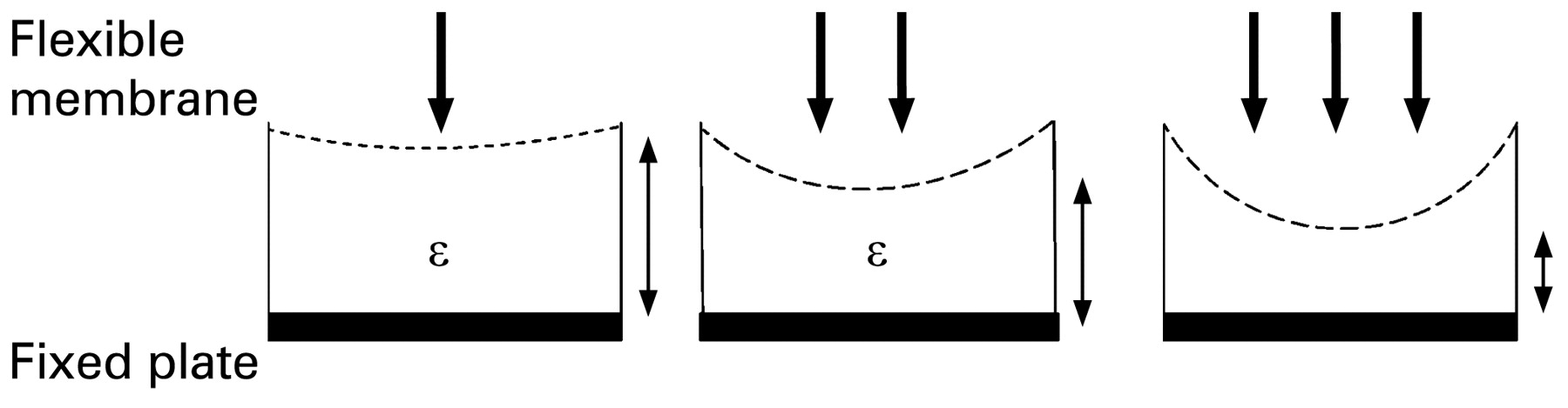
where “C” refers to the capacitance, “A” the area of the plates, “d” the distance between plates and “ε” the dielectric constant of the medium between the plates. In a capacitive pressure sensor, one plate is rigid while the other usually features a thin membrane which deflects when subjected to pressure change. The deflected membrane changes the distance between itself and the fixed plate, resulting in a capacitance change (fig 2).

Schematic of a capacitive type pressure sensor. As the pressure increases (increasing number of bold arrows) the flexible membrane deflects, decreasing the distance to the fixed plate (represented by the diminishing size of the double headed arrows). ε, dielectric constant.
Capacitive-type pressure sensors (C) can be integrated with an inductor (L) to form an LC resonant circuit. The change in capacitance is correlated with resonance frequency (f) given by the aforementioned equation.
The resonant frequency changes in response to the IOP can be tracked remotely via inductive coupling by measuring either the impedance or voltage spectrum across the external antenna.
The development of capacitive pressure sensors has greatly evolved since Collins18 first developed an implantable pressure sensitive radio capsule (transensor) using a pair of parallel, coaxial, encapsulated Archimedean-spiral coils, where a change in the IOP induced a shift in the resonant frequency. More recently, capacitive sensors are fabricated using surface micromachining technology in silicon, as first suggested by Backlundt et al.19 In the past decade, technological developments have led to a programmable IOP sensor system implant integrated on a single complementary metal oxide semiconductor (CMOS) chip.56 The IOP sensor consists of an array of micromechanical vacuum gap capacitors separated by a sealed vacuum cavity. Variations in the diameter of the diaphragm allowed adjustment of the measurable pressure range. This system consists of a sensor implant which contains an on-chip micromechanical pressure sensor, a temperature sensor, readout and calibration electronics, a μC-based digital control unit and radio frequency (RF) transponder all integrated into a single CMOS chip.
Strain-gauge sensors
A strain gauge is a device used to measure deformation (strain) of an object. In order to measure strain with a bonded resistance strain gauge, it must be connected to an electric circuit (eg, Wheatstone bridge circuit) that is capable of measuring extremely small changes in resistance corresponding to strain. The Wheatstone bridge is excited with a stabilised DC supply and zeroed at the null point of measurement. Applied stress unbalances the bridge resulting in a voltage output which is related to the stress. The output voltage is typically a few millivolts requiring additional electronics to amplify the signal level suitable for application to external data collection systems.
Due to the additional electronics and voltage requirements, strain-gauge sensors are not suitable for ocular implantation. Furthermore, a telemetric chip is required for wireless communication to an external device. However, strain-gauge sensors are suitable for non-invasive strategies such as incorporation into a soft contact lens to detect micrometre changes in corneal biomechanics related to IOP. In addition the soft contact lens provides spatial flexibility for additional circuit components. Flower et al used a semiconductor strain gauge bonded to a silicon circling band placed around the equator of the eyeball of the rhesus monkey to establish an accurate IOP profile over long time periods.20
Advancements in MEMS and CMOS-based technology have not only enabled the miniaturisation of pressure sensors but also facilitated the integration of sensor and microelectronics on a single chip. The choice of sensor among researchers depends on the application and system in which it is incorporated. For example, strain-gauge sensors are used in a soft contact lens (non-invasive), and capacitive-based sensors are more commonly used in invasive strategies as part of either an IOL or GDI.
WIRELESS COMMUNICATION
An important consideration for continuous monitoring of IOP lies in the need for wireless communication between the implanted sensor and the external readout device. Wired communication has obvious drawbacks such as increased risk of infection, reduced ocular motility and patient discomfort, which make this approach unacceptable for human usage. In general, biotelemetric systems can be divided into two categories: (1) those based on active sensing devices and (2) those based on passive devices.
In passive telemetry, wireless monitoring of the IOP is achieved through mutual inductance coupling between the inductor on the sensor and the external loop antenna as shown in fig 3. Early passive telemetry systems developed by Collins,18 Rosengren et al21 and Cooper et al1322 were based on the grid dip oscillator technique, which is essentially an RF oscillator that detects the frequency of other oscillators or tuned circuits. However, the accuracy of the above systems was unsatisfactory due to the low quality factor (Q) of the detector circuit, resulting in a low coupling between the external detector circuit and internal antennae leading to a small working distance for communication.

Wireless communication between implanted sensor and external interrogating device.
In active telemetry the transponder includes a transducer, modulator, microprocessor and transmitter as shown in fig 4. The microprocessor converts the analogue signals from the pressure transducer to digital signals for transmission. A power converter converts the electromagnetic energy from the external interrogating device to a current signal to power the microprocessor. The modulator is coupled with the microprocessor and power converter for receiving digitised data from the microprocessor and for modulating the interrogation signal in accordance with the digital data.2324

Schematic of active telemetry wireless communication system.
Several groups have reported an active telemetric integrated system for IOP monitoring.567 Such a system consists of a pressure sensor, signal processing circuitry and RF transponder all on a single chip. These systems are highly miniaturised using flip-chip mounting technology, surface micro-machining or CMOS technologies. The advantages of such systems lie in fulfilling spatial requirements of integrating onto an intraocular lens and also wirelessly communicating though ocular tissue. The spatial requirements in the intraocular lens are such that very small sensors are an absolute requirement, and the output of such sensors requires amplification and signal processing in order to obtain useful data, hence the use of active telemetry.
McLaren et al were the first group to continuously measure IOP in rabbits using a commercial device (Data Sciences International, St Paul, Minnesota). This allowed the researchers to monitor IOP continuously 24 h a day for several months. The results were limited by the battery life of the transducer.25
While active devices are very accurate and sensitive, their complexity, higher power requirements and manufacturing price are the main obstacles to more widespread use.57 Passive devices are typically simpler to construct, cheaper and biocompatible, but they may lack a high degree of sensitivity. Nevertheless, recent investigations and the development of new micromachining techniques and the incorporation of smart materials have increased the effectiveness of the passive approach to a point where it may become feasible.262728
BIOCOMPATIBILITY OF IMPLANTABLE DEVICES
One of the most challenging aspects in implanting sensors is to ensure their long-term biocompatibility. It is well known that surfaces and interfaces are the main determinants of biocompatibility. It is essential to control the response of the tissue in contact with the implant surface. In some cases, cell/tissue adhesion may be desirable in order to hold the implant in place, but in other cases, surfaces should be designed in a way that minimises cell proliferation in order to reduce scarring.
Polydimethylsiloxane (PDMS) has been used extensively to encapsulate IOP sensors.57829 PDMS is biocompatible and deformable, making it an excellent material for implantable applications. Walter et al demonstrated that coating a capacitive pressure sensor with PDMS material did not impair sensor functionality and accuracy. Leonardi et al developed a microstrain-gauge sensor embedded in a soft contact lens made of silicone. The strain gauge was sandwiched between two layers of polyimide, which is an insulating, protecting and flexible carrier material which has excellent properties for biomedical applications. Polyimide offers advantages over other polymers, including its excellent chemical and thermal stability, low water uptake and excellent biocompatibility.15 Meng and colleagues used Parylene C for the design of their IOP sensor due its excellent mechanical flexibility, chemical inertness and biocompatibility.10
CONCLUSION
Implantable sensors are extremely promising tools to revolutionise diagnosis and management of a wide range of diseases. These sensors have substantial theoretical advantages in disease monitoring for conditions such as diabetes and systemic hypertension that would benefit enormously from online data. In the case of glaucoma, a range of sensor technologies have been employed in IOP measurement. These sensors vary from capacitive type sensors, piezoresistive sensors, strain-gauge sensors and Bourdon-tube-based MEMS IOP sensors. These sensors may be incorporated into a system capable of measurement and wireless transmission of data via telemetry.
Many researchers in the field are following a direct (invasive) approach towards IOP monitoring. Such an avenue typically involves a miniature pressure sensor (eg, capacitive pressure sensor) incorporated into a GDI,2430 intraocular lens2431 or even a trabecular shunt32 using wireless communication of data by means of active or passive telemetry. The utility of indirect non-invasive IOP measurement is questionable due to valid concerns related to accuracy and consistency in relating surrogate measurements to actual aqueous hydrostatic pressure.1533 Strategies to develop continuous monitoring for glaucoma patients have in many cases not attempted to act as stand-alone IOP sensors but instead have attempted to exploit multifunctionality, such as the combination of the IOP sensor with an IOL or GDI. The IOL location has size constraints requiring the sensor to be highly miniaturised and therefore requiring active telemetry for wireless communication. The GDI allows greater flexibility in design allowing for a larger antenna coil and sensor to be incorporated in addition to the glaucoma therapeutic utility of the GDI. A passive telemetry approach is suitable in such a case.
With a growing percentage of the population affected by glaucoma, there is a pressing need for continuous IOP measurements to replace the current snapshot techniques like applanation tonometry that are unable to provide ambulatory monitoring due to the need for a skilled operator. It is known that better control of IOP is instrumental in delaying progression of glaucoma and that the current gold-standards of measurement are subject to inaccuracies relating to variations in corneal biomechanics. Ongoing research will in time provide a means of developing a device that will enable continuous monitoring of IOP and should lead to improved management of glaucoma with attendant benefits in reducing glaucoma blindness.
Acknowledgments
I would like to thank R Cooper, for his support, and G Kakaday, for her help with the figures.
REFERENCES
Footnotes
Funding This work was supported by the Ophthalmic Research Institute of Australia and the Australian Research Council.
Competing interests None.